REBUILDING YOUR RADIUS ARMS
October 23, 2024
REBUILDING YOUR RADIUS ARMS.
This little semi technical paper is the result of a Summer of small maintenance jobs that just seemed to expand at an hourly rate. So between four of us we set about saying how Andy the engineer, Tony the metallurgist and unfortunate Dolomite Sprint owner, Me the mechanical engineer and S owner plus James the chemist and Sprite/Midget owner plus Teddy the helper (the Social Sciences grad, so useless at everything!) set about the rebuilding of a set of rear swinging arm assemblies from a donor mini to make a straight swop onto a ’69 S. We’ll go through it and describe some of the tweaks etc etc that we’ve done and other things we encountered during our weekends and evenings. Sadly, none of us studied the finer point of English at Uni so our writing is at best, that which we had in the 6th form – many years ago!
I take it that your grotty rear arms are now on the garage floor, on a large sheet of heavy duty cardboard. Here’s the first tip we learned. Those stout vegetable boxes from the local pick-your- own or garden centre are ideal for supporting the arms while you’re faffing around with them. At the same time, might I suggest that you get the relevant page of the parts list copied and keep them handy. Incidentally, we had a couple of what you teccies would call ‘shagged’ radius arms that we decided to rebuild so as to emphasise the point and then use these as direct replacement units for the not too shagged units that we’d take off the car – if you get my drift! If you keep your eyes peeled, we’ll also be telling you how you can depressurise your hydro system sufficient to remove the radius arms without introducing air into the hydro systen while you do so.
We’ve taken a series of photos of the whole palaver and where necessary, highlighted the salient points that relate to the things we’ve spoken about in particular. We also appreciate that not everyone’s got some of the facilities that we had between us, such as a lathe or a pillar drill so just follow the bits and ideas that take your fancy
Actually stripping the units isn’t too difficult once they’re off the car of course! After that you’ll just need the usual hand tools including a hacksaw. Both brake hoses had to be cut from the right angled supports and one of these had started to crack across the horizontal bend.
Job number 1. Remove broken hose support. These are secured to the arm by two drive rivets which are by definition, very hard. But as a result, will shear off with a blow from a hammer and chisel. You could try slotting and rotating them out with an impact driver or……. We just chopped them off, marked the centres and bored through using a new good quality drill centre to start and an equally good HSS drill to bore through the remains. Then CAREFULLY just tap out to 3/16”or10- 32 UNF. Here’s a little tip. If for some reason you cannot drill the drive rivets out or cannot punch them through after the heads have been sheared, you can move the bracket very slightly rearwards a tad and re-drill and tap new holes into and through the malleable cast arms. It will make no difference whatsoever and if you’re a concourse freak, I don’t suppose anyone would ever notice. But it has saved your swinging arm and any thoughts that you might have to bodge something later.
Now to remove the brake back plate and handbrake cable brackets……, all pretty basic stuff and throw them into a tub of paraffin. Handbrake cable swinging sector….., just tear off the spring fastener or unscrew the nut and bolt and pull these out – if you can. A bit of brute force might well be needed and really, there’s no saving them so before you bin ‘em, put them to one side. We might be saving you £30 quid a bit later. Now, using a long drift or 3” long suitable bolt, gently drift the two brass top and bottom bushes out and keep them handy, with the rusty handbrake sector shafts for later. But one thing you can do now is to ream out the handbrake sector holes through the radius arms. You can do it by holding a 7/16 drill in your hand and working it through the hole (or put it into a drill chuck and work it through slowly) so that you’re clearing the crap and crud out of the hole
The radial axis shafts next. You should be ready to pull them out . But you won’t. So what I suggest is that you use a brass drift and drive them out from the outside/bush end inwards towards the needle roller end. Some say vice verca, but it’s a matter for you. As for removing the bush, well, I haven’t got a special bush remover either so this is what we did and it worked both times, perfectly, first time and easily, even with the grottiest set of rad arms. Find the split (it is a split bush don’t forget) and using a new hacksaw blade with a towel taped around the bit you’re going to use as a handle, CAREFULLY slit along the split in the bush. It’ll cut quite easily and all of a sudden, the bush will close down on the blade indicating that you’re through and it’s given up the fight to remain tight. Now you’ll easily be able to wiggle it out.
As for the needle roller, a similar not-quite-a-bodge! Dislodge the internal grease sleeve outwards or towards one side a bit away from the bearing……, go on, don’t pussy-foot around with it because it’s probably toast already…… and now, you should be able to use the old axis shaft as a drift to sit on the inner edge of the needle roller cage and by tapping it radially, around its inner edge, it’ll slowly come out. Using this method with a really grotty pair of radius arms it took about 15 minutes to remove both bushes and needle rollers
That is your swinging arm stripped and all(?) slowly stirring in the tub of paraffin where you can wash it clean with an old paintbrush. Now leave them to dry. To be honest, it took us a total of two hours on a Sunday afternoon to strip two totally knackered , rusty, tight swinging arm assemblies including cups of tea and a sausage roll!
Now we come to the FIRST BIG problem.
HYDROLASTIC. If you have a hydrolastic car then just as sure as god made little green apples, the Helper Spring Support Pins (or HSSP’s from now on) will be worn away or eroded for obvious reasons and you will see the groove/rut/wear pattern in the bottom half where the helper spring sits. There’s several things that you can do here;
- 1) Live with it
- 2) Replace the stub axle
- 3) Bridge the gap with a brass or stainless bush
- 4) Replace THAT part of the axle shaft.
Drawings for the modified bush have already been shown on the forum.
been tried on a test car over the summer with no ill effect. But in real mechanical terms, it ain’t FIXED the problem, it’s just a palliative and not a cure. If you want to FIX the problem for good then this is what you have to do now.
Get a couple of readily available S rated high tensile steel 3/8” dia UNF threaded allen or hex bolts with at least 1” of thread and 1” of plain shaft and turn the heads off. Now we’re going to simplify matters………. In short, cut off the short stubby and knackered HSSP’s, make good by filing the remains down level with the axle stub that remains and mark the centre of the old stub. Mount on drill press and bore down square into the axle shaft with a pilot drill followed by a 21/64 ” or metric equivalent tapping drill to a depth of 1.25” It’s plain mild steel and easy to drill. While it’s still in the drill press, use the drill chuck to square the tap, start it, and continue by hand, carefully tapping down for the full length of the hole. It really is as simple as that!
The new HSSP’s will screw straight in. The plain end can now be machined to length and to suit the old one you cut off. If you REALLY want to be a martyr, then machine the circlip groove. But if you want to be sensible, just mark and drill through in its place a 2mm hole through which you can insert a readily available stainless ‘R’ clip. Job done. All these stages are shown in the photos. Screw up the new shaft and tighten or locktite.. We’ve shown the new parts PLUS the
We know it works as it’s
steel bush as this what we considered to be mechanically correct – but whether you do is a matter of choice! Best of all, you have replaced the mild steel HSSP’s with high tensile steel.
Would the same idea work for dry suspension axle stubs? Dunno…, we didn’t try but I’m sure the same principle will apply here too
Now is the time to bead blast or wire brush the malleable cast rad arms. You can do it by bead blasting or special steel wire scrubbers fitted to an angle grinder. But take it down to clean white metal. Nothing else is good enough and then paint with red oxide or another protective primer paint. For purely technical and illustrative reasons we very slightly countersunk all of the holes on our grotty examples.
THE SHAFTS AND THE REPAIR KITS. Dear o’ deary me……. The mechanical logic of the shaft bearings really defies explanation for several good mechanical reasons. These reasons have been discussed at some length on the Forum so we won’t prolong the argument. All compounded by the obvious failing that should be clear even to a blind man on a dark night! Total lack of lubrication – or more to the point, lack of lubrication to the outer bush. But, as the saying goes, ‘…..you go to war with what you’ve got…’ So we are going to correct what we have.
The first thing you should do with your new shafts is to mark them directly opposite on both sides of the OUTER end 5/8” – 16mm or so from the start of the main .813” diameter . Grind away a small area with a DREMIL tool and starting with a centre drill followed by a good 1/8” drill, drill right through the shaft, crossing the central grease hole.
First a word of warning. On the better quality shafts such as those kits from MiniSpares for example, the shafts are clearly induction hardened and to a depth of .022”. So be prepared. On the cheaper options, don’t worry, the case hardening isn’t thick and a centre drill cutter drill will easily cut through once the nominally case hardened surface is cut away.
This new grease outlet is directly in the centre of the new bush and aligned with the lubrication recess. What you have to do next is to plug the original outlet hole with a tapered brass rod. Go on….., just hammer it in and make good with a smooth file! Now, the grease gets pumped in via your grease gun as per normal and escapes directly between the shaft and bush – which is JUST where it needs to be and where you want it. End of problem. Does it get better than that?
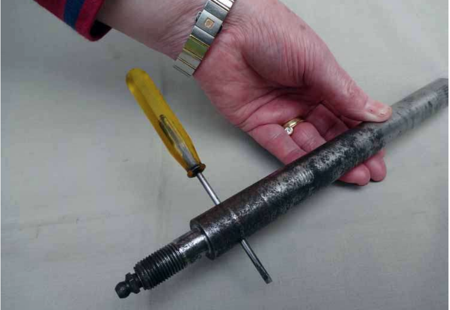
THE INNER END. We do something similar. But this time we break through the case hardening (see above) and drill straight through the shaft 1⁄2” from the start of the main diameter. This time the grease exit hole is directly between the shaft and the needle roller cage. The last thing we have to do here is to drill down centrally into the inner end of the shaft to a depth of 1.75” or 45mm with a 7/32” – 5mm drill when you’ll break into the newly drilled transverse hole you have just drilled. The core of the shaft isn’t hardened so drilling is easy. Tap the outer end 1⁄4 UNF and insert into the tapped hole an angled grease nipple. Now the grease you pump in will go directly into the needle roller and shaft. There, END of problem.
You might now be asking why the need for this modification. The shaft is already greased from the outside anyway. Yes, it is, but………, er……. it isn’t! The grease gets onto the shaft alright via the little hole a couple of inches in from the outer end. Being a liquid, it fills the space outside the shaft, and inside the tube – well, you HOPE it does – and then finds its way backwards (oh no it doesn’t….) towards the bush where it grinds to a stop. That’s because while there is pressure at the grease gun, that pressure just forces the grease to take the line of least resistance, along the shaft, into the needle roller bearing and vent out all over the inner end. With our modified shafts, the grease pumped in from the outer end greases up the outer end bush. Which is JUST what you want! And coincidentally a bit spreads backwards onto the shaft. While the grease pumped in from the outer end goes straight into the inner bearing – which is JUST what you want and again. Coincidentally some will spread out onto the shaft.
Several photographs show an old shaft drilled to the new spec just for illustrative purposes and amply describes all of this. And I must tell you something important now, so listen in!!!!! Make sure that these newly drilled and tapped holes are rinsed in degreaser and brushed (I use those small round tooth cleaner ‘interdental’ brushes from Boots for these jobs) clean and dried with an air-line or aerosol air blaster. Fit the nipples and squeeze through with grease. This will make sure that there’s no swarf left, Got that? Now sit back and admire your work and the simplicity of it all
THE shaft covers. Just a short note here. On the basis that the plastic replacements are said to be total crap, we were able to save one of the steel ones and make a simple repair to the other using a bit of copper pipe. But be advised that making two new replacements is an absolute doddle by using imperial size 1” copper plumbing pipe and the larger diameter bearing-end by soldering on a 1” joiner………. If you can still find the 1” imperial pipe. What you do or what effort you go to is up to you. But it gets better……..
We said a few moments ago that the new style plastic shaft sleeves were crap didn’t we…..? But now, with modified shafts, the balance has changed slightly because now, the plastic sleeves are just a protective cover and not used to guide the grease. So just smear the shaft with grease before assembly and use the new plastic protectors – because that’s all they are now, simple protectors. The bushes and bearings are lubricated directly.
As I mentioned earlier, we didn’t have the special bush and bearing removal tool and neither did we have the replacer tools either although we could have turned them up. But we did have something just as good – in the form of a 300mm/12” length of 10mm threaded rod from our local builders, Sydenhams plus two nuts, cost £3 or so. That rod, the nuts and the old thrust washers taken off the old shafts allowed us to simply pull the greased bush into the greased outer housing. NOW INSERT THE PLASTIC OR STEEL SHAFT COVER. Using the same ploy, pull the greased bearing into the greased inner housing. It really was as simple and easy as that! No hammering or bruising the ends of the bush or bearing, just a slowly-does-it drawing in of the bush and bearing . How simple can it be?
There are a couple of ways that you can ream the outer bush to suit and once again, we didn’t have the correct BMC ‘hand reamer’ tool. That’s the obvious choice of course and if you or your local garage have one or ask your nearest Mini specialist if he’ll do it for you with the special tool then all is well. As the description says, this is a self centring hand reamer that will accurately align the bush and bearing for the shaft.
The alternative is by using a standard ‘engineers’ or ‘machine’ reamer that ain’t self centring! But by inserting the cutter into a lathe head stock , and a rotating centre into the tailstock, centred in the inner-end bearing it will all be aligned due to the very nature of the beast. A slow speed and gently turn the radius arm into the rotating cutter. Simple but if you haven’t done it before or lack a bit of engineering confidence, a specialist Mini workshop will do it for you
Just a quick one next….., as one MP said to the other…….. Oooooops, political joke there. The plastic cups and knuckle joints. On ours, one of the rounded joints and plastic cups only came out with brute force and the housing had rusted around the cup. The other was entirely different. All greasy, nice shiny ball and the cup almost pulled out with it. There’s a lesson there…… Before you reassemble, thoroughly de-rust the steel housing. We used a small Dremil flapper or small emery paper wheel but anything else suitable will do just so long as the rust residue and crap is completely removed. Pack the housing and inside the cup with graphite grease. If the new compressed granular rubber seals are as bad as they are reputed to be, then just use the old ones after a good clean in paraffin, dry off and wash down in clean soapy water.
Why does Tony say graphite grease…..? Good question. Simply because the ball has a small degree of articulation but no rotary movement at all so graphite grease lends itself admiralty to this application. But there’s more. Note GRAPHITE grease as opposed to GRAPHITED grease….. there’s a difference that you’ll see when you handle the relatively thick, semi solid and dark graphite grease v the thin runny graphited stuff.
Remember those rusted out old handbrake sectors that you kept to one side? Now is the time to get them out of the cleaner, wash off and dry. Are the actual SECTOR/Radial parts still OK? If so this is what you do next. De-rivet those rusty old shafts and bin them. Now bore through the hole with 5/16” drill and have a GOOD look at them to make sure that the outer parts aren’t de- laminating from the inner. If they are, they’re toast! What we did now is to replace the 4 brass collars – 1x – top and bottom in each radius arm with newly machined and slightly longer brass bushes. You’ll see on the pictures that the LOWER bush is a ‘top-hat’ bush with the top hat part .1” thick. This is to ensure that the quadrant that rotates slightly is kept slightly clear of the rad arm . You could use a similar thickness brass washer of you wanted to. If you are going to use the original collars, just make sure that they are not elongated inside. These little bushes are subject to a good deal of directional loading wear and do elongate severely. If they rock on the drill shank, they’re toast too. Additionally, the old shaft carries a lot of leverage load when the handbrake is applied. Instead of faffing around with a new pivot shaft we abandoned it and used 4” long stainless steel 5/16” diameter plain shafted bolts UPWARDS, through the old (or new) quadrants, up through the new bushes out through to the top of the rad arm. A stainless washer and a nyloc nut to just nip-up the quadrant and that’s the job done. The quadrant nips up to the new stainless steel bolt that’s free to rotate.
You COULD use a stainless bolt downwards of course…., with the nylock nut at the bottom, supporting the rotating quadrant. But this means that to remove it at some time in the future, the whole rad arm has to be removed. But it’s up to you of course. As an aside, this matter did cause a bit of a discussion. FOR bolt top-to-bottom is that it is less intrusive and leaves more space at the top side of the rad arm between the arm and car body. But space isn’t really a problem here. If it did fail or needed to be removed you could simply(?) loosen it and cut the head off. But then you’d have to revert to the bottom-to-top method we suggested at the start.
We’re near the end, so stay the course for a bit longer…………
The photographs show our progress throughout this rebuild and they’re ready to go. We haven’t touched the brakes or back plates of course but these are straightforward take-off and replace parts that are probably best done when the new arms are fitted. Take the bits out of the paraffin tub and examine them. OK, then re-use them but daub the brake adjuster bolts and segments with coppaslip before re-using them of course. Only you can tell whether to use new wheel cylinders but since you’ve (hopefully) got new hoses it’d be a shame not to replace the cylinders too.
There….. One last bit of advice if I may. Make sure that you cover the grease nipples with those rubber nipple caps. It might seem a trivial point but it is important and shows that the job has been done by someone who knows what he’s doing. Available in packs of 6 or so on that auction site but PLEASE……., what you call nipple covers aren’t quite what other Ebayers are wanting to sell you……….!
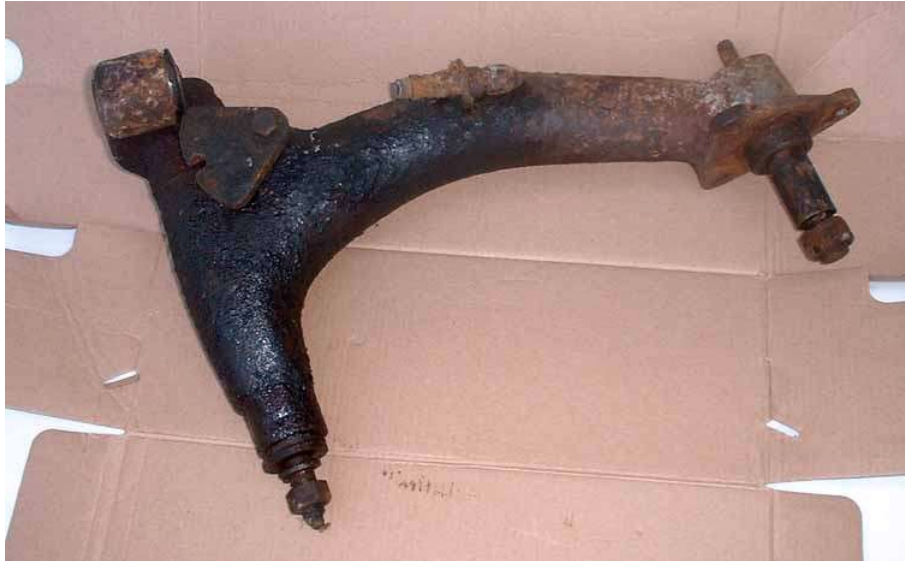
This is how we received out old rear radius arms and how they’ll generally look like on an old Mini. But under all that crap and crud are solid arms and other good parts we’re going to need and some in reasonable condition too.
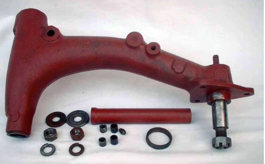
After being stripped, here’s a selection of the parts that we considered serviceable from the arms. Most of the parts shown will come in the new shaft kit and we made new handbrake sector bushes. We did save the second steel shaft sleeve with a bit of judicious tinwork.
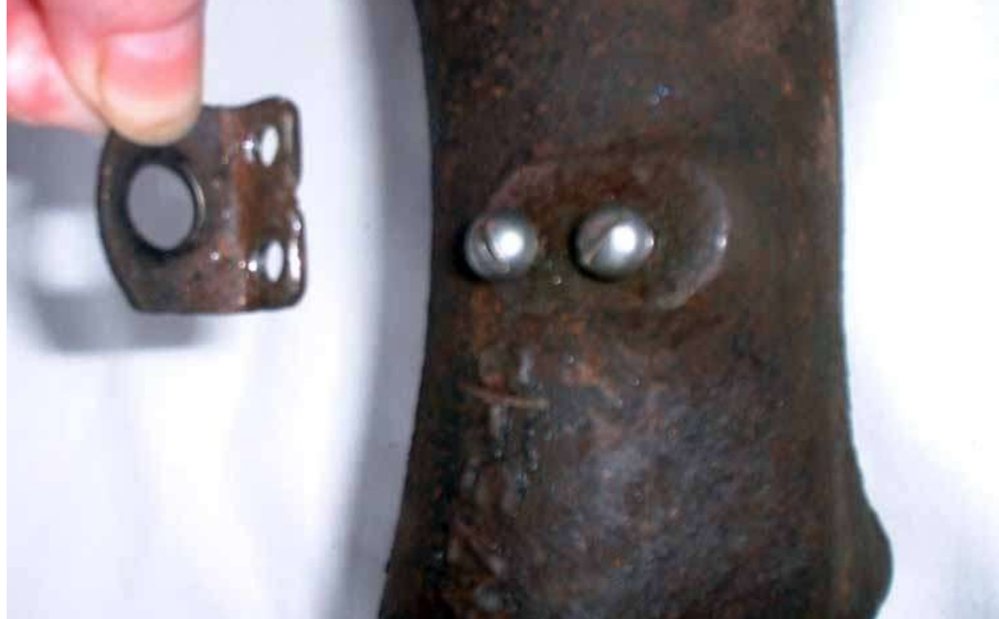
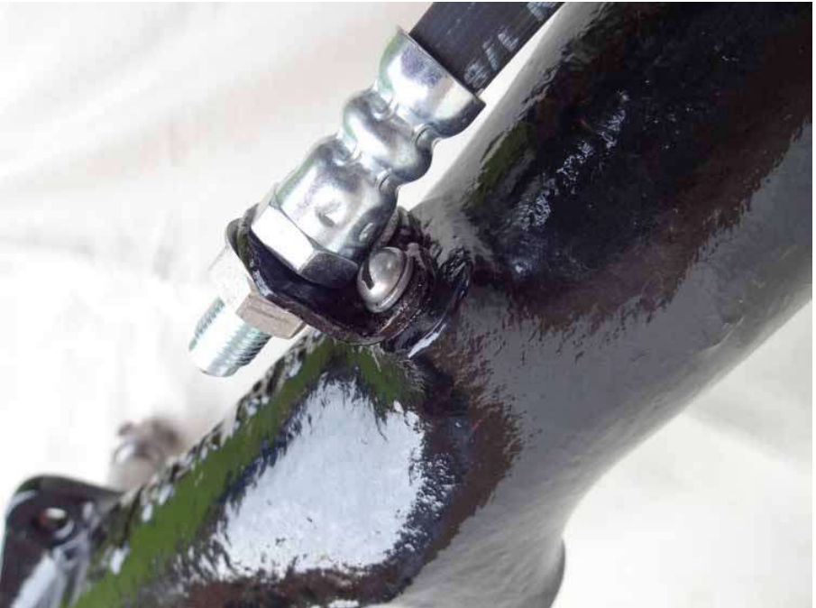
The flexi hose bracket had cracked so we chipped it off, drilled out the drive rivets, drilled and re- tapped for new screws
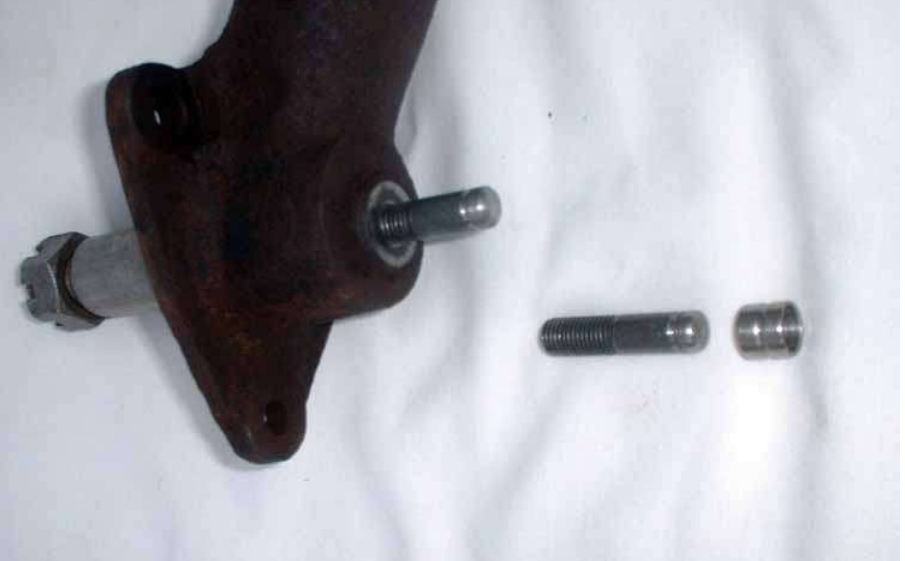
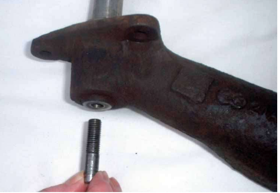
You’ll read in the text how the helper spring support pins were worn away. This picture shows how new ones were simply turned up on a lathe from S rated allen bolts. This time we added a stainless steel bush (you can use brass…) that fits inside the lower helper spring loop and slides over the helper spring support pin. Problem solved! Note also that while we have machined the groove for the circlip for originality, we also drilled through this groove and inserted a simple and more reliable2mm dia ‘R’ clip. Working on the reliability, durability and maintainability theme. But first, a confession. On ours while probably not paying attention we used BSF bolts (26 TPI) instead of UNF (28TPI) but the results were the same
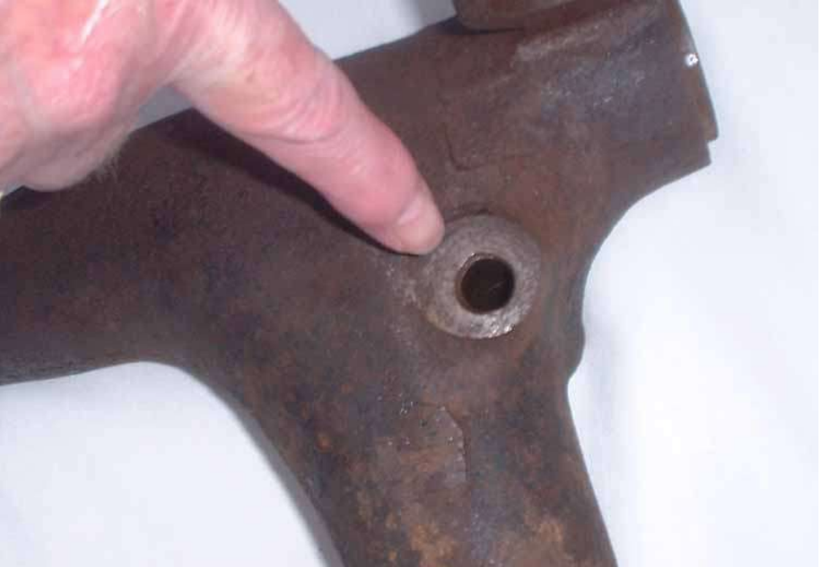
Clear the main axis hole of the handbrake sector with a 7/16 drill shaft to clear out the crud. Later as you’ll see and read we’ll insert a couple of new brass bushes top and bottom here
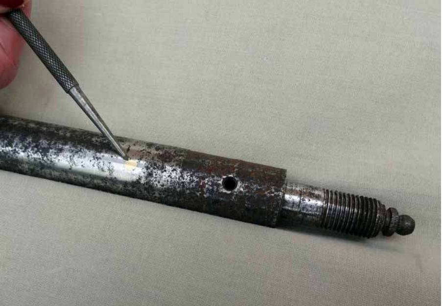
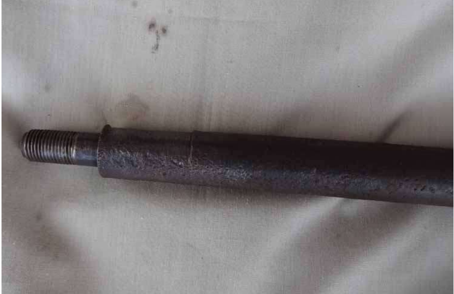
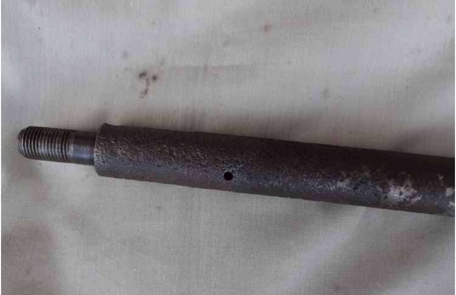
This old axis shaft shows the brass plug punched into the original singe grease outlet. Then the same shaft with TWO new through hole openings (note screwdriver blade) directly under and in line with the central lube recess in the new bush. What on earth were BMC thinking about ……..?

Same shaft again. This time, the INNER end showing the two new grease outlet/vent points directly under and into the central point of the new bearing. Note the angled grease nipple. This can be positioned facing downwards during inserting and alignment of the shaft to ease accessibility from below the car. It will be a simple matter to click a grease gun onto the nipple. As most lads found out early in their lives, you’ll feel the nipples even if you can’t see them.
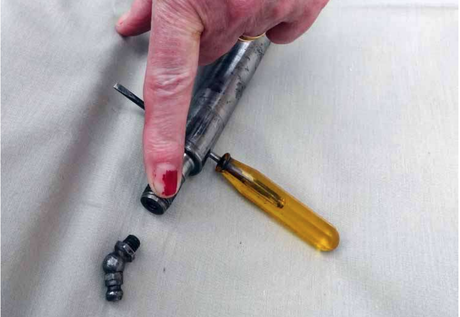

The ends of the shafts are not hardened so drilling in is relatively simple. Just drill in until the drill crosses into the through hole (or vice verca) and tap the thread to suit the grease nipple. Simplicity itself and now the grease is just where you want it. The screwdriver shows the transverse hole while the scriber shows the feed hole, right up to the centre point of the new needle roller bearing. The advantages are simply too numerous to mention. In fact, we’d venture to state that you’ll never need to replace the shafts, bushes or bearings again. Oh yes….., wifey says sorry about her missing nail varnish!
Earlier we told how one of the flexi hose brackets was cracked and was chipped off and replaced. This shows the re-made bracket screwed onto the bead blasted and newly painted radius arm using round headed UNF screws and spring washers. Not that it is important here, but the screw heads also act as an anti-rotation stop for the hose. Don’t make new ones as we did. They’re available from all the parts retailers and Ebay

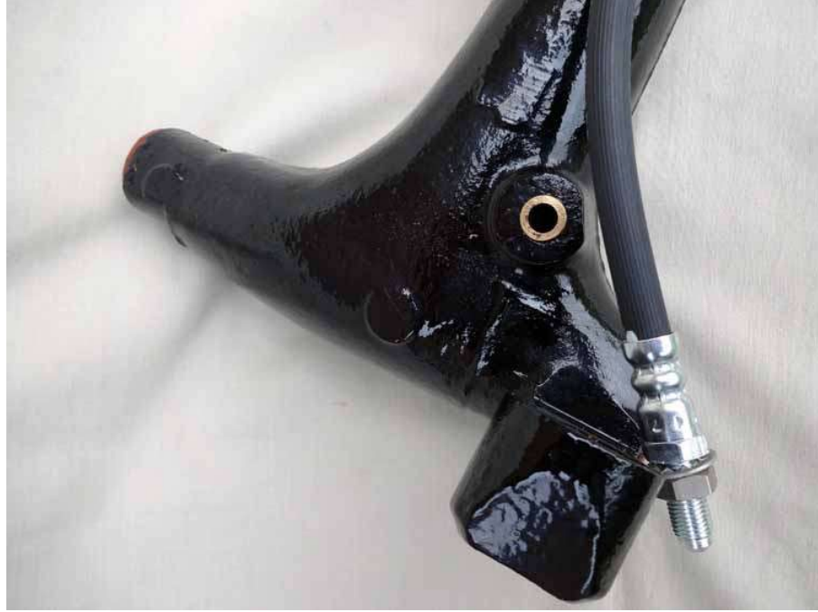
We spoke about the worn out, ovalised handbrake sector shaft bushes earlier. We simply machined 4x new ones but the bottom pair were ‘top-hat’ types. The top hat part replaced the thin washer and serves to keep the rotating cable sector away from the radius arm. A simple thing to do while they were being machined. The cable sector part can now be attached directly to the new stainless steel bolt/shaft which will be nipped up with a stainless nylock nut over a stainless or brass washer. End of problem – for good!
Notice the rusty inside of the knuckle joint cup. We found that a DREMILL tool flapper wheel sat neatly into thus cup and de-rusted it to a white metal shine in 60 seconds flat! Grease it with graphite grease and it will protect it while the plastic cup is in place
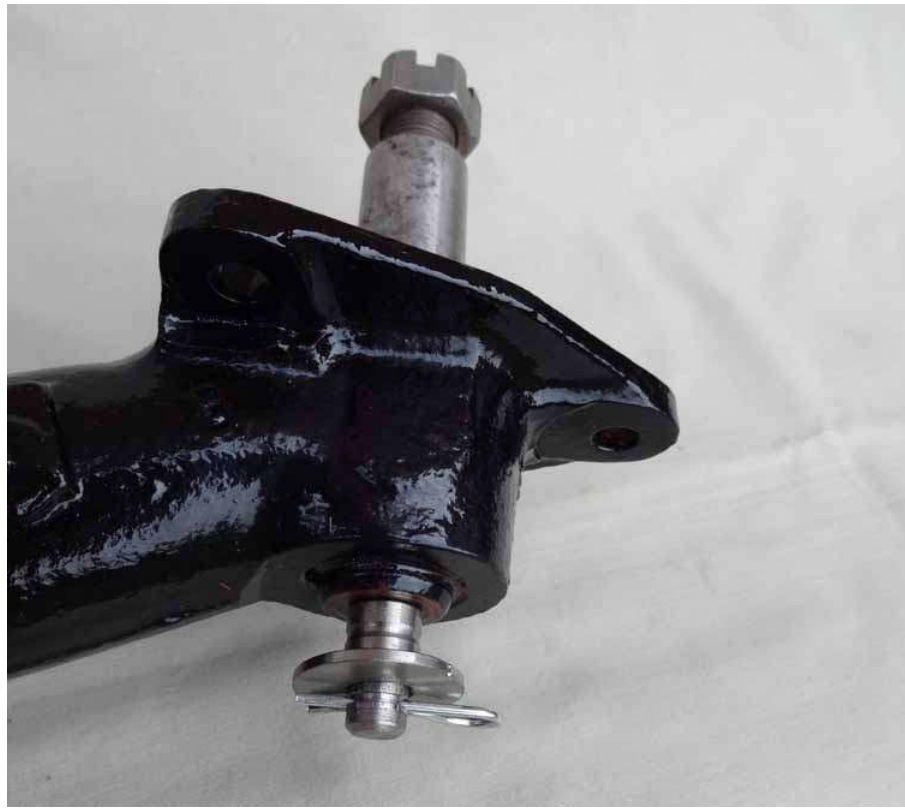
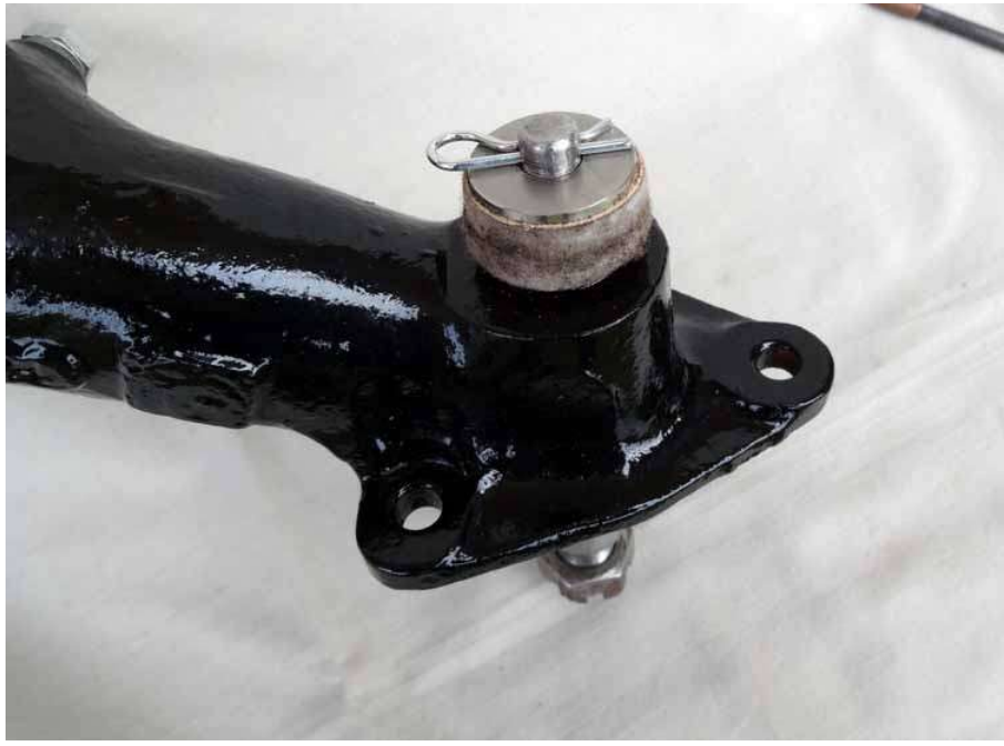
Two views of the new helper spring support peg, the helper spring bush and retaining washer together with the ‘R’ clip that is a far more satisfactory method of retaining whole lot together than the simple circlip or ‘E’ clip. New made oil impregnated felt washers are also shown that will (hopefully) keep the whole lot lubricated and serviceable
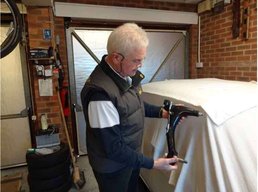
The finished radius arm ready to be fitted to the needy CooperS, covered in the background


We used a morse taper machine reamer. This has to be accurately aligned with the bearing for technical reasons so the bush was reamed on a slow running lathe and pushed in using a tailstock centre to keep things dead square – and accurate!
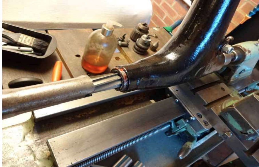
The 13/16” machine reamer and a home made collar to control the depth that the reamer entered the collar. Not strictly necessary….., just old habits die hard!
Just to illustrate the INNER end and the angled grease nipple that will be positioned to point downwards to ease access by the grease gun. No real reason why you cannot use nylock nuts and steel washers on the inner (or both?) ends. Or better still, stainless steel

The outer end. Once again, no reason why nylock nuts cannot be used.
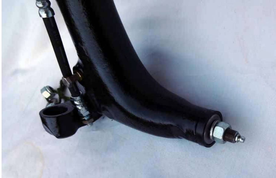
This is the reason for the article in the first place. This absolute farcical nonsense ends here and the day that you rebuild your rear swinging/radius arms. What arrant nonsense from a short sighted fool even imagining that the grease (hole shown) would get within 1” of the bush or even remotely get between the bush and the shaft. Just to reiterate……. The grease, like every other liquid, takes the line of least resistance and…….. oh, don’t get me going…..!.
If you aren’t doing the job yourself, take this article to the builder and tell him THIS is how you want your job done AND that you want to see the modified shaft before he starts the assembly. The extra cost is 1 angled grease nipple and an extra hour of labour.
Peter Laidler (Dec 2017)